View Mesh Graphic Body in Solidworks Drawing
Until recently, the number of SOLIDWORKS users who needed to import mesh files in SOLIDWORKS was relatively small. They would have typically needed to reuse geometry created in an creative modeling software, such as Maya or 3DS Max, or import point cloud files representing scanned data. The process of importing and converting these files to SOLIDWORKS as usable geometry was cumbersome and frustrating, and many times the point cloud would be so large that it could non exist imported into older SOLIDWORKS versions.
With the 3D press revolution, the number of mainstream SOLIDWORKS users who need to insert 3D-scanned models into assemblies, or modify such models, increased exponentially. These "typical" users, accepted to the speed and elegant workflows available when working with SOLIDWORKS models, expressed strong feelings when facing the awkward methods for dealing with mesh files. They likewise developed innovative ideas for repurposing the imported scanned data.
Examples:
- Insert a 3D-scanned part into an associates the fastest mode possible.
- Make up one's mind mass backdrop of the imported model.
- Get measurements from the imported model.
- Apply mates to a 3D-scanned component in an assembly.
- Prove 3D-scanned component in a bill of materials.
- Show 3D-scanned component in a drawing view.
- Attach dimensions to a 3D-scanned component in a drawing view.
- Use imported geometry equally reference for creating SOLIDWORKS native entities.
- Modify geometry originating from indicate cloud files.
"And… could we perform all these operations fast and easy? Thank you!"
SOLIDWORKS is known every bit a company that listens to its user community—almost of its new enhancements are user-driven. It did non take long to discover solutions and enhance the software.
Allow'due south await at the answers provided by SOLIDWORKS 2018 in streamlining these operations, using specific case studies. For more than details and technical terms, please apply this link to access the relevant chapter inside the What'south New in SOLIDWORKS 2018 document.
Challenge 1: Import a Mesh File to Chop-chop Create a Drawing and Dimension the Model
When importing large mesh files, the user should always ask: "What do I demand this file for?" Depending on the answer, he or she could skip over cumbersome converting operations.
The mesh file formats that could be imported in SOLIDWORKS 2018, without the need for accessing the ScanTo3D improver, are shown in Figure i.
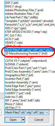 Effigy ane. Type of mesh files that could be imported in SOLIDWORKS.
The most common are:
- STL (Standard Triangle Language, or Standard Tessellation Linguistic communication): Native format for stereolithography CAD
- OBJ: Open-source simple information-format representing 3D geometry alone
- 3MF (3D manufacturing): XML based 3D printing format developed past the 3MF Consortium. In addition to geometry, information technology includes information most material and colors, which could not exist represented in the STL format.
For full control over the way a mesh file would open in SOLIDWORKS, in the Open File dialog, filter by the file type, equally shown in Figure1; do not use the default All Files selection.
Past selecting a certain file type, you get access to the Options button, see Figure ii.
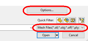 Figure ii. Options button.
Options allow the user to import massive amounts of data as Graphics Bodies, see Effigy iii.
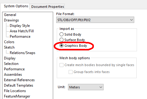 Effigy 3. Options for importing mesh files.
Effigy iv shows the upshot of importing a graphics trunk. The import procedure was almost instantaneous for this model.
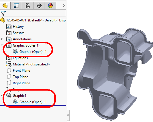 Figure 4. Freshly imported graphics body.
Detect that in add-on to the Graphic i characteristic, SOLIDWORKS collects all the graphics bodies in their own dedicated binder.
Let's change the color of the whole function. The standard workflow for applying and managing appearances has been extended to graphics parts too. Let'due south "paint" information technology xanthous.
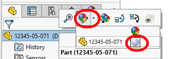 Effigy v. Irresolute the appearance of the part.
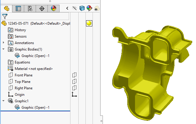 Figure six. Appearance changed at part level.
At this time, appearances cannot be controlled at the graphics body or graphics feature level.
When changing the brandish way for the model in anything other than shaded, the user can encounter the triangular facets that are typical for meshes.
| | |
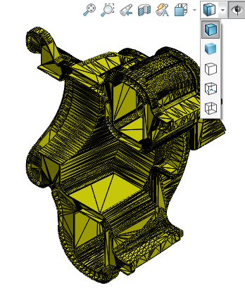
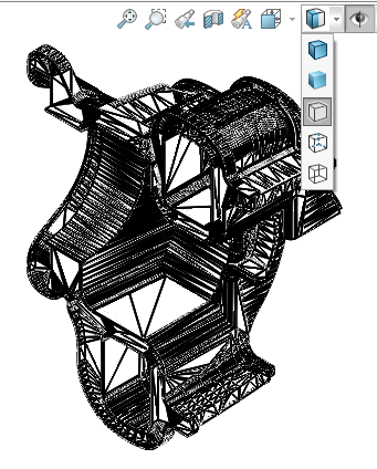
Figure 7. Facets displayed in Shaded with Edges and Hidden Lines Removed.
When working with graphics entities, it is important to be able to select individual facets, edges or vertices from a graphics body. For that, let'southward add specific mesh filters to the filter toolbar.
A quick way to display the filter toolbar is using a keyboard shortcut. The default is F5 (Effigy 8).
Figure 8. The default filter toolbar is missing mesh filters.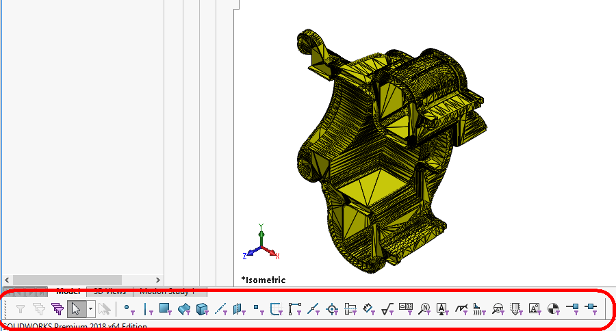
Allow's use the Customize tool for dragging these three icons over the filter toolbar (Figure nine).
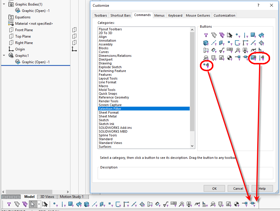 Figure 9
That enables advanced selection abilities for graphic entities (Figure x).
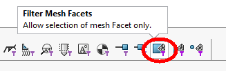

 Figure ten
Notation that at that place is no need to activate such filters when using the Measure out tool (Figure11).
 Figure 11
Permit'south save this part and insert information technology into a cartoon. The offset thing to find is that only draft quality views bear witness graphics bodies. Since SOLIDWORKS needs the body data for calculating the edges of high-quality views, such views volition be empty (Figure 12).
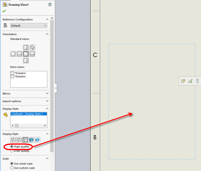 Figure 12. Empty high-quality view.
In one case the view quality is set up to draft, SOLIDWORKS displays the BREP facets directly. All display styles are bachelor: Shaded, Shaded with Edges, HLR, HLV and Wireframe (Effigy 13).
 Figure 13. Draft quality drawing views represented in diverse display styles.
There are serious limitations with what can be washed with a graphics model in a drawing. At this fourth dimension, you lot can only create model views and projected views of such models. Sections, details or other type of views are not currently supported.
Considering in that location are no SOLIDWORKS entities in the model, trying to utilise dimensions will non piece of work. That is the same limitation that one encounters when attempting to dimension SpeedPak assemblies.
The good news is that a similar technique to the one used in preserving SOLIDWORKS entities containing torso data in SpeedPak tin be applied in SOLIDWORKS 2018 for extracting SOLIDWORKS surfaces from graphics models.
Let's switch back to the function environment. In the Command Search file type "mesh" and drag the resulting control over ane of the toolbars to make these specific tools easily accessible (Figure fourteen).
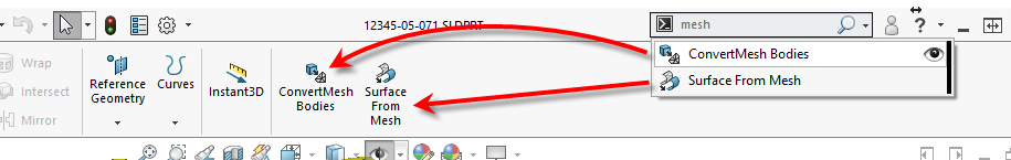 Figure xiv
Now let's create a surface trunk straight from the mesh. I intend to display a dimension on the cartoon representing the thickness of the wall in a sure area. To make the selection easier, I will switch the display way to Shaded with Edges.
Activating the Surface From Mesh control offers the option to rapidly generate different surfaces. Primitives like planar, sphere, cylinder and cone are available. For detailed information on how to use this tool, click here.
In this case, I will try to excerpt a planar face representing the thickness. Since the result volition be a planar face, I will select but on facet and count on SOLIDWORKS to select the remainder of the facets laying in the same airplane and connected to this one (Effigy 15).
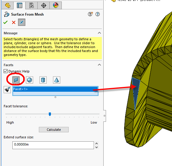 Figure fifteen
The upshot is a SOLIDWORKS surface body, which can be seen in Effigy xvi.
 Effigy sixteen
Let's return to the drawing and apply the dimension to the edges of the surface body (Effigy 17).
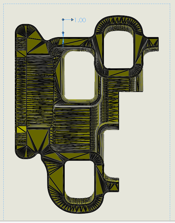 Figure 17
Warning : In SOLIDWORKS 2018 SP0.ane, you might run across a situation where the graphics bodies will be hidden in the drawing views upon a drawing rebuild. I volition report this issue to SOLIDWORKS and study back in the comments section with any possible workarounds.
Challenge 2: Reference the Mesh Entities in Sketches for Creating Standard SOLIDWORKS Features
Allow's create a gasket part that would match the mesh model. For that, follow the steps described in a higher place for inserting the mesh into a new SOLIDWORKS file equally a graphic body.
New in SOLIDWORKS, I can now refer Mesh Facet Vertices in Sketches. First, let's turn the Filter Mesh Facet Vertices on, run into Figure xviii.
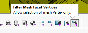 Figure 18
Since the Plane feature does not currently accept a facet, facet border or facet vertex from a graphic body as input, let's ascertain points in a 3D Sketch.
Get-go a 3D Sketch and add 3 Point entities on vertices of the facets where the gasket will exist placed (Figure 19).
 Effigy 19
Use these points to define a new plane (Figure xx).
 Effigy 20
Open a 2nd sketch on the new plane and sketch lines and arcs that have ancillary relations to the facets vertices. Find that relations to the mesh vertices can be inferred but when the viewport is oriented normal to the sketch plane (Effigy 21).
 Figure 21
Once the sketch is created, information technology can be used in defining standard SOLIDWORKS features. See Figure 22.
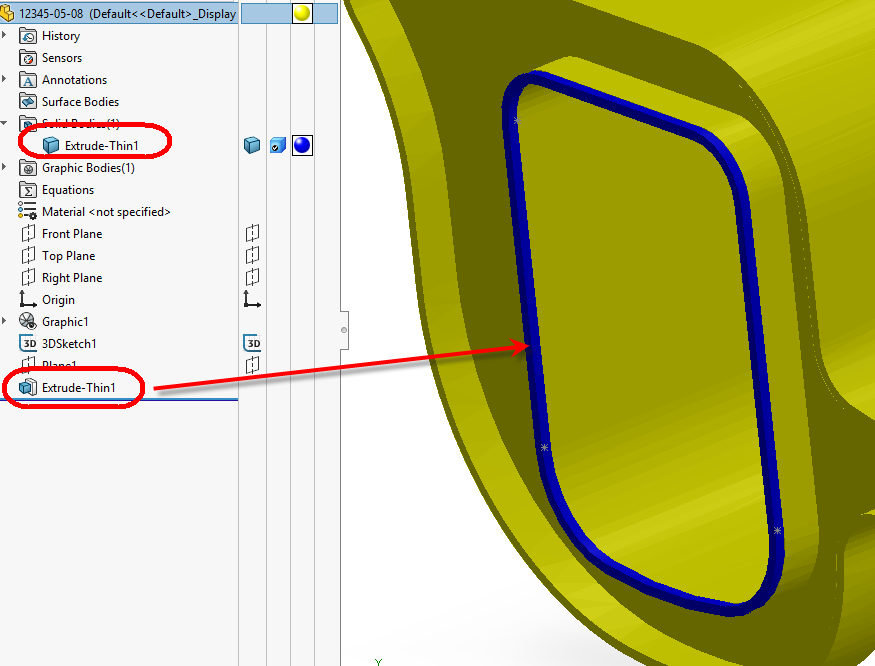 Figure 22
Note: This specific instance study could take been solved faster by using the Surface From Mesh characteristic to excerpt the flat facets of the gasket, followed by a Thicken command (Figure 23).
 Figure 23
The standard SOLIDWORKS planes, sketches, faces, edges and vertices can be easily used in defining mates for such components in assemblies.
This style, the user gets the best of both worlds:
- Speed due to using graphic bodies
- Precision due to using SOLIDWORKS standard entities in mating
It is worth mentioning that Graphic Bodies or components can exist sectioned in function and assembly environments, equally long as the Graphics-only section setting is checked (Figure 24).
 Figure 24
Challenge 3: Change a Mesh File in SOLIDWORKS
The 3D-printing community will be happy to acquire that one of the biggest enhancement in SOLIDWORKS 2018 is the ability to create new mesh bodies and modify existing meshes using Boolean operations.
Permit's add holes to our model before 3D press. For that I will import the model as a mesh (Effigy 25).
 Figure 25
The result is a solid mesh torso (Figure 26).
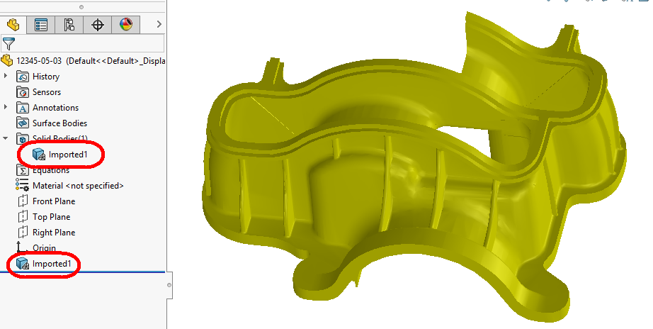 Figure 26
Allow's define the plane for the pigsty orientation based on 3 vertices of a facet (Figure 27).
 Figure 27
In a sketch opened on the newly created aeroplane, I drew a circumvolve representing the hole contour. To fully define the sketch, I added two reference points coincident to 2 vertices in the mesh (Figure 28).
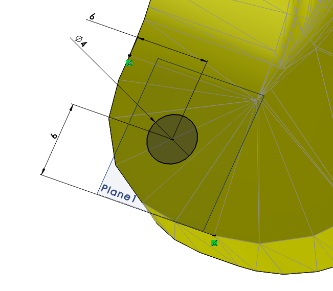 Effigy 28
Let's ascertain the tool for punching the hole past extruding the sketch in both directions (Figure 29).
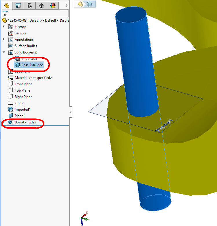 Figure 29
To use a Boolean operation between similar types of bodies, I need to convert the solid trunk of the tool to a mesh body. For that I will use the ConvertMesh Body command (Figure 30).
 Effigy thirty
Allow's subtract the tool from the main mesh body (Figure 31).
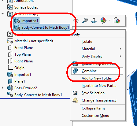 Effigy 31
The upshot is a hole through the original mesh body (Figure 32). Now I can ship this part to the 3D printer.
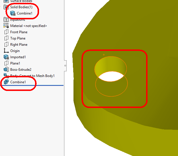 Figure 32
Conclusion
SOLIDWORKS 2018 is a game changer for two types of users:
- Users who piece of work with big signal cloud data and need to:
- Apace insert and precisely mate imported components containing graphic bodies in an assembly.
- Section imported components containing graphic bodies.
- Reference meshes in creating new features or components.
Users who need to chop-chop change the mesh of their models in preparation for 3D printing.
About the Author

As an Elite AE working for Javelin Technologies, Alin Vargatu is a Problem Hunter and Solver, and an avid contributor to the SOLIDWORKS Community. He has presented 19 times at SOLIDWORKS World and tens of times at SWUG meetings organized past four different user groups in Canada and one in the United States. Vargatuis also very active on SOLIDWORKS forums, particularly on the Surfacing, Mold Blueprint, Canvass Metal, Assembly Modeling and Weldments sub-fora. His blog and YouTube channel are well known in the SOLIDWORKS Community.
Source: https://www.engineersrule.com/what-a-fine-mesh-were-in/
0 Response to "View Mesh Graphic Body in Solidworks Drawing"
Post a Comment